
Introduction
This little project will demonstrate how you can use your old NEC IR protocol based TV,DVD or VCR remote control to control you home appliances like fan bulb or virtually anything.
This little project will demonstrate how you can use your old NEC IR protocol based TV,DVD or VCR remote control to control you home appliances like fan bulb or virtually anything.
Consumer IR protocols
There are a number of consumer Infrared protocols out there and they have been used for every single purpose possible i guess, like PDA laptops and other consumer appliances. RC-5 & RC-6 by Phillips , RCA are few examples of consumer IR protocols.
There are a number of consumer Infrared protocols out there and they have been used for every single purpose possible i guess, like PDA laptops and other consumer appliances. RC-5 & RC-6 by Phillips , RCA are few examples of consumer IR protocols.
In this demonstration we will stick the to NEC protocol by NEC corporation,


- A 9ms leading pulse burst (16 times the pulse burst length used for a logical data bit)
- A 4.5ms space
- The 8-bit address for the receiving device
- The 8-bit logical inverse of the address
- The 8-bit command
- The 8-bit logical inverse of the command
- Final 562.5µs pulse burst to show end of message transmission.
Bit Timing
- Logical '0' – a 562.5µs pulse burst followed by a 562.5µs space, with a total transmit time of 1.125ms
- Logical '1' – a 562.5µs pulse burst followed by a 1.6875ms space, with a total transmit time of 2.25
The transmission of 0 and 1 is shown in the image blow

There are four bytes of data bits are being sended in least significant bit first order the figure blow shows the format of an NEC IR transmission frame, for a command of 0xB1 (10110001b) and an address of 0x8D (10001101b) .

16 bits for the address (address + inverse) require 27ms to transmit time .and the 16 bits for the command (command + inverse) also require 27ms to transmit time.
because (address + address inverse) or (command+command inverse) will always contain 8 '0's and 8 '1's so (8 * 1.125ms) + (8 * 2.25ms) == 27 ms .
according to this total time required to transmit the frame is (9ms +4.5ms +27ms+27ms) = 67.5 ms.
Verify with Oscilloscope and logic analyser
the image give blow is take by Rigol DS1052E Oscilloscope 

Logic Analyser shows the timing details
T1 leading pulse at 84.115ms
T2 space on 93.28ms
T3 Address starts at 97.580ms
T4 Address ends , address inverse starts 107.670ms
T5 address inverse ends , command starts at 124.486ms
T6 Command ends, command inverse starts 135.696ms
T7 Command inverse ends and last 562.5µs pulse to show end of transmission

The NEC protocol is so widely used that soon all possible addresses were used up. By sacrificing the address redundancy the address range was extended from 256 possible values to approximately 65000 different values. This way the address range was extended from 8 bits to 16 bits without changing any other property of the protocol. The command redundancy is still preserved. Therefore each address can still handle 256 different commands.in extended protocol instead of sending address and address inverse we send address low and address high as shown in the image blow.

Repeat Codes
If the key on the remote controller is kept depressed, a repeat code will be issued, typically around 40ms after the pulse burst that signified the end of the message. A repeat code will continue to be sent out at 108ms intervals, until the key is finally released. The repeat code consists of the following, in order:
A 9ms leading pulse burst
A 2.25ms space
A 562.5µs pulse burst to mark the end of the space (and hence end of the transmitted repeat code).
the figures give blow show the timing of repeat codes
.jpg)
if user keeps the key depressed the repeat codes keep coming
.jpg)
T8 shows the timing of repeat code

Decoding NEC Protocol with microcontroller
Decoding NEC is really easy ,there are certainly various methods to do, some examples i have see n used polling method in which the firmware keep polling the input pin of microcontroller which connects to IR sensor , other method is to user interrupt ,in this demonstration we will be using the interrupt method as this one is better, we will be using interrupt on change.
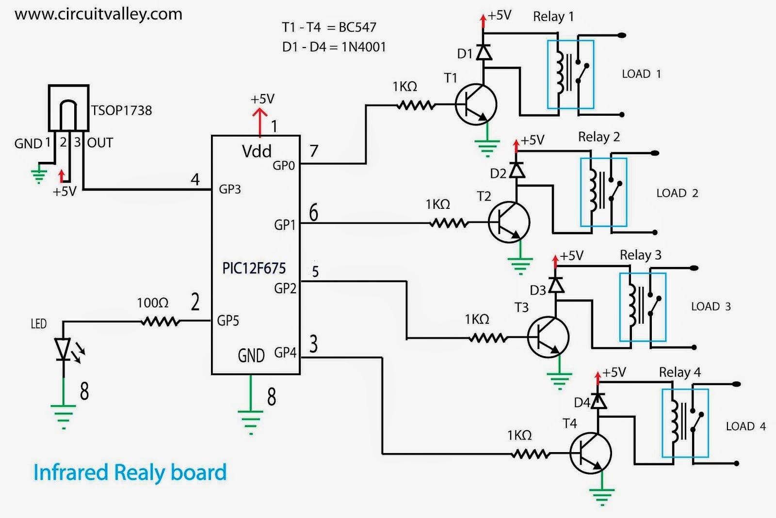
Schematic :
Because of power supply , Decoupling capacitor 100nF and 10uF is recommended on pin 1 and GND , as point out by readers.
.jpg)
SOFTWARE
GitHub Repo
PROTOTYPE


There has been a extension to this project
12 Channel Relay + 2 Channel Dimmer control by IR Remote and keyboard
.jpg)
DEAR SIR,
ReplyDeleteI need serial out code for 12f675 to send data over serial GPI1 pin of 12f675.
pls help me out to write serial transmission ocde for 12f675
pic12f675 does't have hardware UART , so you have to implement software UART.
Deletedear sir pls share code for soft uart
Deletethanks®ards
vishal
i don't have source code for Soft uart , specifically PIC12F675 right now and currently have no plan to develop any one of them. in near future
Deleteif you need any other thing else please let me know
Dear Sir please give your Email Address....
DeleteMy Mail : ashikbsl@live.com
Circuit work krega
DeleteDear Sir,
ReplyDeleteHave you written code for this NEC IR decoder in other PICBASIC Pro or CCS compiler?
if yes pls share.
I have written the source code in hi tech c , and it is open source ,available to download from the link on the page.
DeleteI have not written the source for any other compilers or language . But I guess you can easily convert the code into any of them
Where is the transmitter circuits?
ReplyDeleteplease read the post , this circuit is to reuse the nec protocol based remote controls. so the transmitter may be your tv's remote.
DeleteWhich tv remote?i've programmed the ic with the code given by u, i use Phillips rc5 remote,but it doesn't working,pls tell about remote.
ReplyDeleteoh its working,thanks for ur nice project,but i get only 3 output,pls tell me which remote can work 4 output?
ReplyDeletethere are 4 outputs , but if wanted to have more outputs then there are lots of ways to achieve that
Deletecan you share one of the way to achieve that? more than 4 channel outputs?
Deleteuse a 74HC595 shift register or use a SPI , I2C port expander
DeleteSir i am tried with sundirect remote and old vcr remote haier lcd tv remote but still not working what we have to set in pic programming config like bandgap, oscillator
ReplyDeleteHello Sir, I have download the code file and compiled with HT PIC but it showing error
ReplyDeleteThe error as follows..
ReplyDeleteBuild C:\Documents and Settings\Hades\Desktop\RC5\NEC IR RECEVER SOURCE\NEC IR Receiver.mcw for device 12F675
Using driver C:\Program Files\HI-TECH Software\PICC\9.80\bin\picc.exe
Make: The target "C:\Documents and Settings\Hades\Desktop\RC5\NEC IR RECEVER SOURCE\main.p1" is out of date.
Executing: "C:\Program Files\HI-TECH Software\PICC\9.80\bin\picc.exe" --pass1 "C:\Documents and Settings\Hades\Desktop\RC5\NEC IR RECEVER SOURCE\main.c" -q --chip=12F675 -P --runtime=default --opt=default,+asm,-debug,-speed,+space,9 --warn=0 -D__DEBUG=1 --addrqual=ignore -g --asmlist "--errformat=Error [%n] %f; %l.%c %s" "--msgformat=Advisory[%n] %s" "--warnformat=Warning [%n] %f; %l.%c %s"
Error [192] C:\Documents and Settings\Hades\Desktop\RC5\NEC IR RECEVER SOURCE\main.c; 71.4 undefined identifier "INTCONbits"
Error [196] C:\Documents and Settings\Hades\Desktop\RC5\NEC IR RECEVER SOURCE\main.c; 71.19 struct/union required
Error [196] C:\Documents and Settings\Hades\Desktop\RC5\NEC IR RECEVER SOURCE\main.c; 74.17 struct/union required
Error [196] C:\Documents and Settings\Hades\Desktop\RC5\NEC IR RECEVER SOURCE\main.c; 76.25 struct/union required
Error [192] C:\Documents and Settings\Hades\Desktop\RC5\NEC IR RECEVER SOURCE\main.c; 78.1 undefined identifier "GPIObits"
Error [196] C:\Documents and Settings\Hades\Desktop\RC5\NEC IR RECEVER SOURCE\main.c; 78.15 struct/union required
Error [196] C:\Documents and Settings\Hades\Desktop\RC5\NEC IR RECEVER SOURCE\main.c; 80.17 struct/union required
Error [196] C:\Documents and Settings\Hades\Desktop\RC5\NEC IR RECEVER SOURCE\main.c; 81.15 struct/union required
Error [192] C:\Documents and Settings\Hades\Desktop\RC5\NEC IR RECEVER SOURCE\main.c; 96.1 undefined identifier "OPTION_REG"
Error [192] C:\Documents and Settings\Hades\Desktop\RC5\NEC IR RECEVER SOURCE\main.c; 100.1 undefined identifier "INTCONbits"
Error [196] C:\Documents and Settings\Hades\Desktop\RC5\NEC IR RECEVER SOURCE\main.c; 100.17 struct/union required
Error [196] C:\Documents and Settings\Hades\Desktop\RC5\NEC IR RECEVER SOURCE\main.c; 101.17 struct/union required
Error [196] C:\Documents and Settings\Hades\Desktop\RC5\NEC IR RECEVER SOURCE\main.c; 102.17 struct/union required
Error [196] C:\Documents and Settings\Hades\Desktop\RC5\NEC IR RECEVER SOURCE\main.c; 103.17 struct/union required
Error [196] C:\Documents and Settings\Hades\Desktop\RC5\NEC IR RECEVER SOURCE\main.c; 104.17 struct/union required
Error [196] C:\Documents and Settings\Hades\Desktop\RC5\NEC IR RECEVER SOURCE\main.c; 105.16 struct/union required
Error [192] C:\Documents and Settings\Hades\Desktop\RC5\NEC IR RECEVER SOURCE\main.c; 110.1 undefined identifier "EECON1bits"
Error [196] C:\Documents and Settings\Hades\Desktop\RC5\NEC IR RECEVER SOURCE\main.c; 110.15 struct/union required
Error [192] C:\Documents and Settings\Hades\Desktop\RC5\NEC IR RECEVER SOURCE\main.c; 128.12 undefined identifier "GPIObits"
Error [196] C:\Documents and Settings\Hades\Desktop\RC5\NEC IR RECEVER SOURCE\main.c; 128.27 struct/union required
Error [196] C:\Documents and Settings\Hades\Desktop\RC5\NEC IR RECEVER SOURCE\main.c; 128.44 struct/union required
i think there is some problem in including header files for the project or you imported wrong header file or selected the wrong target device
Deleteplzzz help me how to decode NEC protocol stepwise plzzz help thnx in advance
ReplyDeleteSir the source code is well commented please go through the post and the source code together i hope you will get it
DeleteAs I get data from another remote?
ReplyDeleteyou can use any NEC remote you like , as long as you know the hex commands remote send . to know that you can use scope.
DeleteThis comment has been removed by the author.
ReplyDeleteyou read all 32 bits or only the part of the command?
ReplyDeletei read all the 32 bits and verify them.
DeleteNice project
ReplyDeleteI do have Car mp3 NEC protocol remote and hex command send are:
CH- 45, CH 46, CH+ 47
Prev 44, Next 40, Play/Pause D9
Vol- 07, Vol+ 15, EQ D9
0 16, 100+ 19, 200+ 0d
1 0C, 2 18, 3 5E
4 08, 5 1C, 6 5A
7 42, 8 52, 9 4A
Will work with your program?
Hi,
ReplyDeleteThanks for Nice project, Can we use 12F629 instead of 12F675 if ADC is not used and it is pin to pin compatible with same amount of flash.
Thanks,
Raghavendra
hello i want to detect all 2 bits and display on lcd, but you have give 4 o/p ports, then how can i interface with 8 ports of lcd...please any body give me suggestion as soon as possible...my email id bchavda5@gmail.com
ReplyDeleteif you want to interface lcd with only 2 pins then follow this post blow
ReplyDeletehttp://www.circuitvalley.com/2011/12/two-wire-serial-lcd-16x2-graphics.html
but i guess you need to modify both of the source so that both IR decoder and LCD driver both can fit into this tiny mcu's flash.
so i recommend you to use bigger mcu,at least big in terms of flash size .
Hello friend! this variable command corresponds to which part of the drawing above?
ReplyDeleteWhat do I need to change the control to view the picture in the link?
ReplyDeletehttps://www.dropbox.com/s/rii08u14zuew4cr/20130211-234658.bmp
very nice projects,
ReplyDeletei've used it to control light & fan,
but what should i do for fan speed control by using pwm,
how can i write code for 3 toggle sw & 1 sw for fan speed control
This comment has been removed by the author.
DeleteHi !
ReplyDeleteNice project!I buid this and now I like to make one with momentary-on: turn the associated channel on for the time the button is being pressed .
Can u help me with asm for this function?
Thanks in advance.
nice but when power off,its unable to remain previous state,what should i do to remain previous state.
ReplyDeleteI guess you should use latched relay for that.
Deleteit should reinstate in the state is got shout down, as we have used eeprom to store previous state.
Deletevery nice project but there is some confusion regarding the circuit diagram. Pin4 of pic12f675 is used for both ir receiver and the output transistor ,how it is possible.Pl reply with the correction if needed.Thanks
ReplyDeleteNo. 4 repeatedly
ReplyDeleteHow can it work repeatedly?
Deleteplease explain.
hi gourav,
ReplyDeletei try your hex code,but it is not working :( , is there any precaution have to be taken at the time of programming? i am using pickit2 programmer.i also try to compile it by hi-tech c but i also get the same error as Hades org got.
do you have RC5 code for the same type of projects?
Thanks for the code. I have implemented it for PIC16F877A and PIC16F628A and it is working almost fine. Only there is some problem occurs when certain 2-3 keys of remote are pressed, sometimes the receiver does not respond. It hangs. Also plz if you can give suggestion to detect the key release of remote button. For example I have to do certain task only till remote button is pressed. Once the button is released the task to stop.
ReplyDeleteThis comment has been removed by the author.
DeleteHI, Could you please provide the code for pic 16F877A. It would be great help. Please do needful.
Deleteplease send me your code for pic16f877
Deletemail id- praveenp924@gmail.com
Please send me that your code for pic16f877a
DeleteThis comment has been removed by the author.
ReplyDeleteIs it a standard that every remote control like Philips,Sony etc transmits data with the carrier frequency of 38 KHz? If not what other carrier frequencies are used
ReplyDeleteits not about the brand , its about the protocol they use i mean all the
DeleteNEC based IR will use 38Khz
RC-5 IR protocol use 36Khz
RCA IR protocol use 56Khz
Sony SIRC protocol use 40Khz
i universal remote i believe will go from 36Khz to 40Khz
different frequency for ir may be
25KHz
33KHz
36KHz
38KHz
56Khz
38Khz is most common
Nice Project, work pretty fine. More grace to your elbow sir
ReplyDeleteGreat project, I am using 16 bit extended address protocol IR remote and i have modified the instruction if((!(address & notaddress)) && (!(command & notcommand))) to if(!(command & notcommand))only but i can not get it up to run.
ReplyDelete2)The indication LED will blink when i press a button from my IR remote but I cannot turn off any LEDs.
3)I do not have a scope to read the code sent from my remote. I m using Arduino's IR remote program written by Ken Shariiff to read the code, again my PIC12f675 is not turning off any LEDs.
I have been debugging this for weeks, advice is needed. Anyone please help. Thank you.
you are not able to turn them off only ? or can not change the state at all?
DeleteThanks for your reply. I cannot change the state at all.
DeleteWhen i power up the PIC12f675, three LEDs will light on and when i press a button on my IR remote,the LED attached to gpio5 will blink once. When i press any other button,the rest of the other LEDs still lighting on.
Firstly, #define TICKSPERMS 1004, It is actually 1000 na. 1 usec for each inc.
ReplyDeleteSecondly, tdiff = ((timer<<8)+TMR0) ; This right shifting brings higher value na.
1. its not "#define TICKSPERMS 1004 " it is "//#define TICKSPERMS 1004" its commented please pay little attention.
ReplyDelete"It is actually 1000 na. 1 usec for each inc" where did i mention that 1us for each increment, who told you that boy?
it may be true only and only if the oscillator is absolute at 4Mhz but its not its +-1% so tweak the value for the mcu i have. and i am very sure you did't understand NEC protocol otherwise you must have known that these delay values are need not to be absolute spot on.
2. "This right shifting brings higher value na" what does this even means? please use some technical word to specify your concern.
code has no error or bugs at all.
First of all, Thanks Mr Gaurav for early reply. I understood the TICKSPERMS clearly now. I'm sorry for not using technical word.I am iterating your code and got stuck often. I'm beginner on IR Protocol. Hopefully soon I will achieve NEC through my continuous efforts and your help.
DeleteThe second doubt is..
Timer overflow occurs for every 256 usec. For Eg., we are continuously receiving 0 and 1 from IR Transmitter. At that case timer count would be 4+TMR0 (0) and 8+TMR0 (1).
tdiff = ((timer<<8)+TMR0); At this step the tdiff value for 0 is 1024+TMR0 and for 1 is 2048+TMR0.
In the If Condition we are checking as if ((tdiff>8032) && (tdiff<11044)), at this point i feel the condition will never become true.
I am trying to convert yours to PIC16F877A. Please don't get angry,I am sure that something i am ignoring on this well working code. Please help me out.
this code is quite old and seems to be well proven to work and not to stuck any where , as we used interrupt for most of the job. the state machine never comes across any dead state, even if something wrong happen interrupt will take care of that. for a bit more recovery mechanism you can use WDT if you like ,at cost of a bit extra cost of code memory.
Deletebefore we can talk about timer just let me tell you is simple variable that hold how many times TMR0 (hardware TIMER) is overflowed , and TMR0 is the register that hods count for hardware TIMER.
hardware TIMER does overflow ~256us but timer variable never,it just stuck at highest value. timer variable increment at every overflow of timer.
if you see this mathematically then this may look like, when lsb for a number get overflow carry goes to next higher significant digit. for decimal if lsb wanted to above 9 then it turn back to zero and carry out to higher significant digit.
so when i add (timer <<8) + TMR0 this expression will produce total number of micro seconds . if you have 9ms of time then you will have 35 in timer variable and 40 in TMR0 register so to add them this is what you have to do
(35*256)+40 = 9000us
so i believe that if the 9ms leading pulse is between 8ms to 11ms (tdiff>8032) and (tdiff<11044)
<<8 operation is same as *256
<<8 operation is required to get the timer value up to its significant.
you never add 32000 +40 = 72 (wrong)
you always add every digit to same significant digit.
yes TIMER does over flow at ~ 256us and at every 256us it increment variable
i still did't understand few for your words properly but still i will try to explain a bit
"At that case timer count would be 4+TMR0 (0) and 8+TMR0 (1).
tdiff = ((timer<<8)+TMR0); At this step the tdiff value for 0 is 1024+TMR0 and for 1 is 2048+TMR0. "
if timer variable have 4 and TMR0 is 0
4+TMR0 means =( 4*256 )+0 = 1024 us
8+TMR0 means = (8*256) +1 = 2049 us
i am not angry , don't worry i just get too stright some times. sorry for that
This comment has been removed by the author.
DeleteThis comment has been removed by the author.
DeleteThanks a lot Mr Gaurav, You took plenty of time to reply. But sorry to say, my doubt is not clarified. I hope mistake is mine, i am not conveying proper. Let me clearly ask you again..
ReplyDeleteInterrupt begins now. IR Receiver TSOP1738 is active low.
**9ms pulse has come,So INT pin goes low, Falling Edge Triggered "INT"
Timer count is 35, So (35*256)+40 = 9000us
if condition "" (tdiff>8032) and (tdiff<11044) "" True
** After 9ms, 4.5 ms Space, At the end of 4.5ms space,The Next falling Edge happens we are starting to receive 0's and 1's for 32 times
**1.125 ms for both pulse and space for Logic 0
Timer count is 4, So (4*256)+101 = 1125us
if condition "" (tdiff>8032) and (tdiff<11044) "" Fails here..
Same for Logic 1
**2.25 ms for both pulse and space for Logic 1
Timer count is 8, So (8*256)+202 = 2250us
if condition "" (tdiff>8032) and (tdiff<11044) "" Fails here..
once it fails, it may not receive the command and address because, The following code present inside the if loop discussed above.
*************************************************************************
if(tdiff>1250)
{
rxbuffer = rxbuffer | 0x1;
}
else
{
rxbuffer = rxbuffer |0x0;
}
************************************************************************
Hope this time i conveyed my doubt clearly. Again thanks for your valuable time.
as i said before please pay little attention
Deleteits not if (tdiff>8032) and (tdiff<11044)
its if ((tdiff>PREPULSE) && (tdiff<TIMEOUT) )
PREPULSE and TIMEOUT variable get updated as per that state of the machine.
are you aware of programming? of any kind.
HI GAURAV!
ReplyDeleteVery interesting and impressive work!!
I need your help, i don't know if you can help me!
I am trying to create a sensor to detect IR packets!
and also send IR packets! Those at 56Khz!
My IR TX range must be around 35feet!
I am planing to use PIC microcontrollers!
what you suggest for the IR devices and PIC!?
thank you
Hi,
ReplyDeletei am using pickit2 programmer to programed the hex code.is there any setting need to be done before programming?
no additional settings are need to be done just burn the hex, all the configuration bits are present in the hex file
Deletesir pls help me some error found
DeleteICDWarn0020: Invalid target device id (expected=0x7E, read=0x0)
ICDWarn0044: Target has an invalid calibration memory value (0x0). Continue?
...Reading ICD Product ID
Running ICD Self Test
...Passed
MPLAB ICD 2 ready for next operation
And one more thing how can make a dimmer using 12f675 microcontroller?do u have any code for this?
ReplyDeleteat this particular instance i don't have any code for dimmer
DeleteYes I am having dimmer code for PIC16f722A. Phase angle is changed by PIC MCU and 10k pot.
Deletekrunal_c_thummar@yahoo.com
Hi Gaurav Chaudhary, Nice Job Done. The Code is Excellent. One Important thing is. If the customer is pressing Volume or Channel Up and Down, Then NEC protocol will issue repeated pulses. How to get that logic implemented. It's needed na..? Awaiting for your reply.
ReplyDeleteThanks for supporting.
yeah you need to do something to detect repeat pulses. i have't implemented it , for this sort of application you can get away without implementing it. there are various ways to do it.
DeleteHi Gaurav, I'm happy with your earliest reply. Please help me out.
ReplyDeleteThank for the code! its really helpful. very clean and neat explanation
ReplyDeletegood post! thank you
thank for the code! its really helpful. very clean and neat explanation
ReplyDeleteI just want to glow a LED through IR sensor or transceiver using uC 16f877 or 16f88 in microC...please provide me the microC code and proteus simulation also so that i can implement its hardware....thanks in advance
ReplyDeletei am afraid that i don't use microC, so i am unable to provide anything with that.
DeleteThank you
In 2007 I build a similar project. I suggest to you to use an ULN2003 instead of resistor+bjt+diode. I wrote the code entirely in assembler. Feel free to take a look at my project.
ReplyDelete(use google translate to translate italian to english)
http://www.tattik.altervista.org/infra4.html
www.tattik.it
hi,
ReplyDeletenice project,
i want the same project using 8051 or 8052 mcu (eg: p89v51rd2 or 89c51), using c language.
please send me, my email is: regs1613@gmail.com
thank you.
Hi,
ReplyDeletei want to replace existing keypad from my digital clock to nec remote. My question is that whether i have to add the decoding code with my current program or use a decoder ic and connect it to my PIC ?. which one is better, because the decoding is complicated since it deals with usec and msec, also i am using timer interrupt to display in 7 seg display so there is a chance of missing reception interrupt.
please reply,
thanks and regards
Nikhil.
i am comming with the same problem as hades. while compiling it is showing :-
ReplyDeleteundefined identifier "INTCONbits" etc.
can you please suggest which verson of MPLAB & HI tech compiler u are using. aslo i cross varify the header files etc all seems to be correct. i have selected pic12f675.
please help.
Sir My name is Ashwin from India
ReplyDeleteI try your hex code it is working with pic12f675 ok ,but it is not working with pic16f628A
plzzz help me how to change code i don't understand hi tech c language.....
please reply,
My Email. ashwinp25@gmail.com , ashwin_turbo@yahoo.com
thanks and regards
Ashwin
Sir My name is Ashwin from India
ReplyDeleteI try your hex code it is working with pic12f675 ok ,but it is not working with pic16f628A
plzzz help me how to change code i don't understand .....
please reply,
My Email. ashwinp25@gmail.com , ashwin_turbo@yahoo.com
thanks and regards
Ashwin
Hi Gaurauv, I'd like to use two output pins for driving a little DC motor, pressing one button it turns clockwise, pressing another button it turns counterclockwise. I develop a simple circuit with 4 PN2222 transistor and some resistors and diodes. how can i modify your C-code to get ON state just on pressing one button? I tried something like:
ReplyDeletecase 0x50: RELAY1 = 0;
RELAY2 = 0;
RELAY3 = 0;
RELAY4 = 0;
RELAY1 = 1; //on relay 1
RELAY1 = 1; //on relay 1
RELAY1 = 0;
and so on but it doesn't work.
Please, Can you suggest me something else?
Hi Gaurauv, I studied much more your code. Compliments for comments and for all your work, WELL DONE!!
ReplyDeleteI understand that i didn't need to save GPIO output state in internal eprom so i commented that lines when "dataready" is 1 i disable interrupt, turn on the right relay (switch-case), delay (__delay_ms) for 400ms and re-enable interrupt. I added "else" (on dataready=0) to set all RELAY*=0 but i can't get it working well!
May you suggest me something more?
Thanks in advance and best regards
Giorgio
This comment has been removed by the author.
ReplyDeletehello nice project, and 'can do with a change in the code to store the state of the relay even when you switch off the circuit? so as to get back the same state to its restart. thanks GianniUndo editsIs this translation better than the original?Yes, submit translationThank you for your submission.
ReplyDeleteSalve!-interjection
The state has already saved in internal eprom at every "change"
DeleteHi Gaurauv, I spent more times on code analisys. The receiver dosen't manage "repeatcode" of NEC IR protocol, while the transmitter does it. May you help me on "repeatecode" managing? So I'll able to keep GPIO ON state when repeatcode received. Thanks in advance and best regards.
ReplyDeleteGiorgio
for receiver side i did't implemented repeat code because , for this particular application ( latching type control) we don't need one. but if you are willing to use this code for momentary ON type control then you need have significance of the repeat code.
DeleteThis comment has been removed by the author.
DeleteThank you very much for your reply, may you help me on C code for manage repeat code? I have to modify the routine "void interruptOnChangeIsr(void)" but I don't understand completly the code, May you suggest me something more? Maybe it's something about necpoj variable, how can i check when repeat code is receive? Thanks in advance
DeleteGiorgio
Hi Gaurav, I studied much more your code and I understand it completely. Now I tried to recompile the source code and write it in PIC12F675 but it doesn't work. If I use the original compiled HEX file everything is OK, but with compiled mine NOT.
DeleteIs there any issue on compiling? Should I set something in MPLAB IDE or Hi.Tech C compiler? Thanks in advance and best regards.
Giorgio
usually there is no need to set any thing it should compile directly out of the box.
Deletebut still you may try to create a new MPLAB project and add only main.c file into your newly created project and see what happens.
if it still did't work then show me your compilation log , i will find a solution for you
Hi Gaurav, thank you very much for your reply!
DeleteI started a new project, selected the work dir, the compiler and imported only the main.c file.
These are verbosed compiling steps:
Clean: Deleting intermediary and output files.
Clean: Deleted file "D:\Users\Giorgio\Documenti\Receiver\RECEIVER.mcs".
Clean: Done.
Build D:\Users\Giorgio\Documenti\Receiver\RECEIVER for device 12F675
Using driver C:\Program Files (x86)\HI-TECH Software\PICC\9.83\bin\picc.exe
Trace is enabled; scanning project files for __TRACE and __LOG statements.
Executing: "C:\Program Files (x86)\HI-TECH Software\PICC\9.83\bin\picc.exe" --pass1 "D:\Users\Giorgio\Downloads\NEC IR REMOTE\NEC IR RECEVER SOURCE\main.c" -q --chip=12F675 -P --runtime=default,+clear,+init,-keep,+osccal,-download,-resetbits,-stackcall,+clib --opt=default,+asm,-debug,-speed,+space,9 -v --warn=3 -D__DEBUG=1 --double=24 --float=24 --addrqual=ignore -g --asmlist "--errformat=Error [%n] %f; %l.%c %s" "--msgformat=Advisory[%n] %s" "--warnformat=Warning [%n] %f; %l.%c %s"
cpp -W3 "\"--edf=C:\Program Files (x86)\HI-TECH Software\PICC\9.83\dat\en_msgs.txt\"" -DHI_TECH_C -D__PICC__ -D__PICCPRO__ -SP1,1,1,1,1,1,1,1 -D__DEBUG=1 "\"-IC:\Program Files (x86)\HI-TECH Software\PICC\9.83\include\"" -E1 -D_OMNI_CODE_ -D_HTC_VER_MAJOR_=9 -D_HTC_VER_MINOR_=83 -D_HTC_VER_PATCH_=0 -D_HTC_EDITION_=0 -D_12F675 -D_MPC_ -D_PIC14 -D_PROGMEM_=3 -D_HAS_OSCVAL_=1 -S1,2,2,3,4,3,3 -D_COMMON_=0 -D_BANKCOUNT_=2 -D_BANKBITS_=1 -D_GPRBITS_=0 -D__DATABANK=1 -D__FLASHTYPE=3 -D_ROMSIZE=1024 -D_EEPROMSIZE=128 -DEEPROM_SIZE=128 -D_FLASH_ERASE_SIZE=1 -D_FLASH_WRITE_SIZE=1 "\"D:\Users\Giorgio\Downloads\NEC IR REMOTE\NEC IR RECEVER SOURCE\main.c\"" main.pre
p1 -W3 "\"--edf=C:\Program Files (x86)\HI-TECH Software\PICC\9.83\dat\en_msgs.txt\"" -v -Tunsupported,s -E1 -S -u -fp -Gstrings,const -M -B -J -Y -r -RI -QP,bank0 -QX,bank1 -QY,bank2 -QZ,bank3 -QE,eeprom -QF,far -QN,near -QI,interrupt -QS,persistent -QCu,const -QE,eeprom main.pre main.p1 C:\Users\Giorgio\AppData\Local\Temp\s2rg.2
del C:\Users\Giorgio\AppData\Local\Temp\s2rg.
del C:\Users\Giorgio\AppData\Local\Temp\s2rg.1
del C:\Users\Giorgio\AppData\Local\Temp\s2rg.2
Executing: "C:\Program Files (x86)\HI-TECH Software\PICC\9.83\bin\picc.exe" -oRECEIVER.cof -mRECEIVER.map --summary=default,-psect,-class,+mem,-hex --output=default,-inhx032 main.p1 --chip=12F675 -P --runtime=default,+clear,+init,-keep,+osccal,-download,-resetbits,-stackcall,+clib --opt=default,+asm,-debug,-speed,+space,9 -v --warn=3 -D__DEBUG=1 --double=24 --float=24 --addrqual=ignore -g --asmlist "--errformat=Error [%n] %f; %l.%c %s" "--msgformat=Advisory[%n] %s" "--warnformat=Warning [%n] %f; %l.%c %s"
HI-TECH C Compiler for PIC10/12/16 MCUs (Lite Mode) V9.83
Copyright (C) 2011 Microchip Technology Inc.
(1273) Omniscient Code Generation not available in Lite mode (warning)
cgpic -W3 "\"--edf=C:\Program Files (x86)\HI-TECH Software\PICC\9.83\dat\en_msgs.txt\"" -Og9s -q -E1 -w9 -PMS0:code@CONST=00h-0FFhx4 -PMS0:code@CODE=00h-03FFh -PMS0:code@STRCODE=00h-03FFh -PMS0:code@ENTRY=00h-0FFhx4 -PMS0:code@STRING=00h-0FFhx4 -PMS1:data@BANK0=020h-05Dh -PMS1:data@RAM=020h-05Dh -PMS1:data@ABS1=020h-05Fh -PMS1:data@COMMON=05Eh-05Fh -PMS1:data@SFR0=00h-01Fh -PMS1:data@SFR1=080h-0DDh -PMS2:eedata@EEDATA=00h-07Fh/02100h -PMS3:config@CONFIG=02007h-02007h -PMS4:idloc@IDLOC=02000h-02003h -PPICCP12F675,2,1024,2,8,0,0,0 -fp -AC:\Users\Giorgio\AppData\Local\Temp\s2vk. --addrqual=ignore --runtime=init --runtime=clear main.p1 "\"C:\Program Files (x86)\HI-TECH Software\PICC\9.83\lib\eeprom/ee12f675-p.lpp\"" "\"C:\Program Files (x86)\HI-TECH Software\PICC\9.83\lib\htpic--c.lpp\""
cgpic -W3 "\"--edf=C:\Program Files (x86)\HI-TECH Software\PICC\9.83\dat\en_msgs.txt\"" -q -E1 -DRECEIVER.sdb -PMS0:code@CONST=00h-0FFhx4 -PMS0:code@CODE=00h-03FFh -PMS0:code@STRCODE=00h-03FFh -PMS0:code@ENTRY=00h-0FFhx4 -PMS0:code@STRING=00h-0FFhx4 -PMS1:data@BANK0=020h-05Dh -PMS1:data@RAM=020h-05Dh -PMS1:data@ABS1=020h-05Fh -PMS1:data@COMMON=05Eh-05Fh -PMS1:data@SFR0=00h-01Fh -PMS1:data@SFR1=080h-0DDh -PMS2:eedata@EEDATA=00h-07Fh/02100h -PMS3:config@CONFIG=02007h-02007h -PMS4:idloc@IDLOC=02000h-02003h -PPICCP12F675,2,1024,2,8,0,0,0 -AC:\Users\Giorgio\AppData\Local\Temp\s2vk. --addrqual=ignore --runtime=init --runtime=clear main.p1 "\"C:\Program Files (x86)\HI-TECH Software\PICC\9.83\lib\eeprom/ee12f675-p.lpp\"" "\"C:\Program Files (x86)\HI-TECH Software\PICC\9.83\lib\htpic--c.lpp\""
Deleteaspic -W3 "\"--edf=C:\Program Files (x86)\HI-TECH Software\PICC\9.83\dat\en_msgs.txt\"" -E1 "\"-CC:\Program Files (x86)\HI-TECH Software\PICC\9.83\dat\picc.ini\"" -ver=V9.83 -lRECEIVER.lst --opt= --chip=12F675 -R400 -I -no_bankop -no_pa --prog=00h-03FFh -oRECEIVER.obj C:\Users\Giorgio\AppData\Local\Temp\s2vk.
aspic -W3 "\"--edf=C:\Program Files (x86)\HI-TECH Software\PICC\9.83\dat\en_msgs.txt\"" -E1 "\"-CC:\Program Files (x86)\HI-TECH Software\PICC\9.83\dat\picc.ini\"" -ver=V9.83 --opt= --chip=12F675 -R400 -I -no_bankop -no_pa --prog=00h-03FFh -oC:\Users\Giorgio\AppData\Local\Temp\s2vk.obj C:\Users\Giorgio\AppData\Local\Temp\s2vk.as
hlink -W3 "\"--edf=C:\Program Files (x86)\HI-TECH Software\PICC\9.83\dat\en_msgs.txt\"" -cs -h+RECEIVER.sym -z -w9 -Q12F675 -MRECEIVER.map -E1 -ACONST=00h-0FFhx4 -ACODE=00h-03FFh -ASTRCODE=00h-03FFh -AENTRY=00h-0FFhx4 -ASTRING=00h-0FFhx4 -ABANK0=020h-05Dh -ARAM=020h-05Dh -AABS1=020h-05Fh -ACOMMON=05Eh-05Fh -ASFR0=00h-01Fh -ASFR1=080h-0DDh -preset_vec=00h,intentry,init,end_init -ppowerup=CODE -pfunctab=CODE -ACONFIG=02007h-02007h -pconfig=CONFIG -DCONFIG=2 -AIDLOC=02000h-02003h -pidloc=IDLOC -DIDLOC=2 -AEEDATA=00h-07Fh/02100h -peeprom_data=EEDATA -DEEDATA=2 -posccal=03FFh -DCODE=2 -DSTRCODE=2 -DSTRING=2 -DCONST=2 -DENTRY=2 -k C:\Users\Giorgio\AppData\Local\Temp\s2vk.obj RECEIVER.obj
aspic -W3 "\"--edf=C:\Program Files (x86)\HI-TECH Software\PICC\9.83\dat\en_msgs.txt\"" -E1 "\"-CC:\Program Files (x86)\HI-TECH Software\PICC\9.83\dat\picc.ini\"" -ver=V9.83 --opt= --chip=12F675 -R400 -I -no_bankop -no_pa --prog=00h-03FEh -oC:\Users\Giorgio\AppData\Local\Temp\s2vk.obj C:\Users\Giorgio\AppData\Local\Temp\s2vk.as
hlink -W3 "\"--edf=C:\Program Files (x86)\HI-TECH Software\PICC\9.83\dat\en_msgs.txt\"" -cs -h+RECEIVER.sym -z -Q12F675 -ol.obj -MRECEIVER.map -E1 -ACONST=00h-0FFhx3,0300h-03FEh -ACODE=00h-03FEh -ASTRCODE=00h-03FEh -AENTRY=00h-0FFhx3,0300h-03FEh -ASTRING=00h-0FFhx3,0300h-03FEh -ABANK0=020h-05Dh -ARAM=020h-05Dh -AABS1=020h-05Fh -ACOMMON=05Eh-05Fh -ASFR0=00h-01Fh -ASFR1=080h-0DDh -preset_vec=00h,intentry=04h,init,end_init -ppowerup=CODE -pfunctab=CODE -ACONFIG=02007h-02007h -pconfig=CONFIG -DCONFIG=2 -AIDLOC=02000h-02003h -pidloc=IDLOC -DIDLOC=2 -AEEDATA=00h-07Fh/02100h -peeprom_data=EEDATA -DEEDATA=2 -posccal=03FFh -DCODE=2 -DSTRCODE=2 -DSTRING=2 -DCONST=2 -DENTRY=2 -k C:\Users\Giorgio\AppData\Local\Temp\s2vk.obj RECEIVER.obj
objtohex -W3 "\"--edf=C:\Program Files (x86)\HI-TECH Software\PICC\9.83\dat\en_msgs.txt\"" -i -16,2 l.obj RECEIVER.hex
hexmate -W3 "\"--edf=C:\Program Files (x86)\HI-TECH Software\PICC\9.83\dat\en_msgs.txt\"" RECEIVER.hex -E1 -ORECEIVER.hex -logfile=RECEIVER.hxl -addressing=2
cromwell -W3 "\"--edf=C:\Program Files (x86)\HI-TECH Software\PICC\9.83\dat\en_msgs.txt\"" -k -m -P12F675,2675,PIC14 -NCONST,CODE,STRCODE,ENTRY,STRING RECEIVER.hex RECEIVER.sym -omcof -E1
del l.obj
Memory Summary:
DeleteProgram space used 262h ( 610) of 400h words ( 59.6%)
Data space used 22h ( 34) of 40h bytes ( 53.1%)
EEPROM space used 0h ( 0) of 80h bytes ( 0.0%)
Configuration bits used 1h ( 1) of 1h word (100.0%)
ID Location space used 0h ( 0) of 4h bytes ( 0.0%)
del C:\Users\Giorgio\AppData\Local\Temp\s2vk.
del C:\Users\Giorgio\AppData\Local\Temp\s2vk.1
del C:\Users\Giorgio\AppData\Local\Temp\s2vk.2
del C:\Users\Giorgio\AppData\Local\Temp\s2vk.as
del C:\Users\Giorgio\AppData\Local\Temp\s2vk.obj
Running this compiler in PRO mode, with Omniscient Code Generation enabled,
produces code which is typically 40% smaller than in Lite mode.
The HI-TECH C PRO compiler output for this code could be 244 words smaller.
See http://microchip.htsoft.com/portal/pic_pro for more information.
Loaded D:\Users\Giorgio\Documenti\Receiver\RECEIVER.cof.
********** Build successful! **********
I erased the pic, checked for blank and write new .hex file but it still doesn't work. All test LEDS connected to output pins remain always ON.
May you suggest something more?
Thanks in advance and best regards.
Giorgio
Build seems to be okey,
Deletemay be any of these reasons could be the issue.
1. if the status led is blinking when you hit the button then may be ,you are sending the IR command which is not compatible, or the remote you are using is not NEC protocol.
2. any of the component is faulty. try to change the PIC and IR sensor too.
3. the PIC is using internal oscillator as clock source may be the osccal values got very rong thats why micro did't even started. this happen in PIC12 devices a lot . so try to run a simple blink led and see if it works fine.
4. power supply could also be issue.
i will add repeat code in the receiver side too as soon as i get time..
DeleteHi Gaurav, thank you very much for your reply. If I use your original .hex file everything work fine! I tested just two push button on your remote control and with original hex (compiled) I turn on and off two leds on pin 6 and 7 on reveciver side. So I think hardware is ok, what about you?
DeleteI've already tried with three different PICs and the status led always blink on receiving signal.
I'm quite sure on code developed by me for repeat code but it doesn't work cause issue on original latched function. It works perfectly with original .hex but doesn't work with compiled code... very strange!
Giorgio
I tried to recompile again and reprogram PIC. The strange thing is that your original hex file is 3kb while my compiled hex file is 4kb.
DeleteI'm using MPLAB IDE v8.92 and HiTech C Compiler v 9.83.
Which versions are your usually using for compiling C code files? Thanks a lot for support and kindly!
Giorgio
i have pro version of the compiler , but this can't be the issue for operation.
DeleteHI-TECH C Compiler for PIC10/12/16 MCUs V9.83 Copyright (C) 2011 Microchip Technology Inc
DeleteBut the only difference are PC, compilers and the PIC PROGRAMMER... your hex file is OK, it works fine! My hex file doesn't work... the only difference is a compile myself file... may you email your well function C file? Is the same attached in the downloadable file? My email is gtraldi at g mail dot COM. Thanks a lot.
Deletehere it is
Deletehttps://github.com/circuitvalley/IR-Remote-Control
Hi Gaurav, thanks a lot for your patience and kindness! That's incredible thing!!!!
DeleteI activated the PRO MODE on Compiler, now my hex file is 3Kb like yours one:
Executing: "C:\Program Files (x86)\HI-TECH Software\PICC\9.83\bin\picc.exe" --pass1 D:\Users\Giorgio\Documenti\Receiver\main.c -q --chip=12F675 -P --runtime=default --opt=default,+asm,-debug,-speed,+space,9 --warn=0 -D__DEBUG=1 -g --asmlist "--errformat=Error [%n] %f; %l.%c %s" "--msgformat=Advisory[%n] %s" "--warnformat=Warning [%n] %f; %l.%c %s"
Executing: "C:\Program Files (x86)\HI-TECH Software\PICC\9.83\bin\picc.exe" "-oNEC IR Receiver.mcw.cof" "-mNEC IR Receiver.mcw.map" --summary=default --output=default main.p1 --chip=12F675 -P --runtime=default --opt=default -D__DEBUG=1 -g --asmlist "--errformat=Error [%n] %f; %l.%c %s" "--msgformat=Advisory[%n] %s" "--warnformat=Warning [%n] %f; %l.%c %s"
HI-TECH C Compiler for PIC10/12/16 MCUs (PRO Mode) V9.83
Copyright (C) 2011 Microchip Technology Inc.
Licensed for evaluation purposes only.
This licence will expire on Fri, 07 Feb 2014.
Warning [1090] D:\Users\Giorgio\Documenti\Receiver\main.c; 86. variable "_rep_tdiff" is not used
Warning [1090] D:\Users\Giorgio\Documenti\Receiver\main.c; 84. variable "_rep_notcommand" is not used
Memory Summary:
Program space used 1A5h ( 421) of 400h words ( 41.1%)
Data space used 21h ( 33) of 40h bytes ( 51.6%)
EEPROM space used 0h ( 0) of 80h bytes ( 0.0%)
Configuration bits used 1h ( 1) of 1h word (100.0%)
ID Location space used 0h ( 0) of 4h bytes ( 0.0%)
Loaded D:\Users\Giorgio\Documenti\Receiver\NEC IR Receiver.mcw.cof.
********** Build successful! **********
Now my compiled file is working well!
So, HiTech C in Lite mode doesn't create working file, HiTech C in Pro mode creates working file!
Now I'll try to implement the repeating code mangament modifying your code.
Thanks in advance
Best regards
Giorgio
if ( (tdiff>PREPULSE) && (tdiff2 && necpoj<68) //now we are picking the data
Delete{
necpoj++; //necpoj sill inrement on every edge
if(necpoj&0x01) // here we check the if necpoj is an odd number because when necpoj goes greater then 3 then
//necpoj will always be and odd value when a single bit tranmission is over
{
rxbuffer=rxbuffer<<1; //shift the buffer
if(tdiff>1250) //we are here means we just recevied the edge of finished tranmission of a bit
// so if last edge was more than 1.24 ms then the bit which is just over is one else it is zero
{
rxbuffer = rxbuffer | 0x1;
// GPIObits.GPIO5 = !GPIObits.GPIO5;
}
else
{
rxbuffer = rxbuffer |0x0;
// GPIObits.GPIO4 = !GPIObits.GPIO4;
}
}
if(necpoj >66) // we have reached (Leading pulse 2 +address 16+~address16+ command 16+ ~command 16+ last final burst first edge 1)=67th edge of the message frame means the date tranmission is now over
{
address = (rxbuffer>>24)& 0xFF; //extract the data from the buffer
notaddress = (rxbuffer>>16)& 0xFF;
command = (rxbuffer>>8) & 0xFF;
notcommand = (rxbuffer) & 0xFF;
rxbuffer=0; //clear the buffer
if((!(address & notaddress)) && (!(command & notcommand))) // check weather the received data is vaild or not
{
// tutto ok, salvo i dati per poter utilizzarli dopo per il repeat
//rep_address = address;
//rep_notaddress = notaddress;
rep_command = command;
//rep_notcommand = notcommand;
dataready =1;
}
else
{
// c'e' stato un error, quindi azzeriamo dati salvati precedentemente
//rep_address = 0;
//rep_notaddress = 0;
//rep_command = 0;
//rep_notcommand = 0;
dataready=0;
}
TIMEOUT = TICKS11ms; // weather we received the vaild data or not we have to reset the state machine
PREPULSE = TICKS8ms;
REP_TIMEOUT = TICKS2o7ms;
REP_PREPULSE = TICKS1o8ms;
necpoj=0;
}
}
else
{
TIMEOUT = TICKS11ms; // some error occured reset state machine
PREPULSE = TICKS8ms;
REP_TIMEOUT = TICKS2o7ms;
REP_PREPULSE = TICKS1o8ms;
}
}
else
Delete{
if(pin==0) //we are here means that after a longtimeout or PREPULSE we just detect a pulse which may be the start of 9ms pulse
{
//rep_tdiff = tdiff;
necpoj = 1; // yes it could be the start of 9ms pulse
}
else
{
necpoj = 0; // no it's not start of 9ms pulse
}
address = 0xFF;
notaddress = 0xFF;
command = 0xFF;
notcommand = 0xFF;
dataready = 0x000;
TIMEOUT = TICKS11ms; //default timing
PREPULSE = TICKS8ms;
REP_TIMEOUT = TICKS2o7ms;
REP_PREPULSE = TICKS1o8ms;
}
}
hi i have program file NEC IR Receiver.mcw.hex and test with led but all 4 led power on only status led power off and blink when i push key on remote.why 4 led to contron relay alway power on please help me
ReplyDeleteare you using remote control provided by me ,or using some generic NEC remote , may be you remote control's commands codes are not match to the commands we are using in here
Deletethank for your reply i have edit my remote code and it run very good thank you
ReplyDeletequite fast you are!!!!
Deletein the receiver code where "define ADDRESS" value (address for the Data Framing) ?
ReplyDelete@Gaurav Chaudhary: boss can u please tell me the actual model number or full description of NEC remote controller. What i've to tell to the shopkeeper to find the actual remote controller. thanx
ReplyDeletethere is no such model or serial number , i pick one remote from local market
Deleteyou can make your own remote if like
http://www.circuitvalley.com/2013/09/nec-protocol-ir-infrared-remote-control.html
oki boss! so plz tell me the description of the remote that you picked from local market i mean for which TV is the remote for!
Deleteprejudice and 'can do get out of a 4-door BCD code that changes every time you change the channel, to drive an external decoding? thanks
ReplyDeleteyes this is possible.
Deletecould you kindly make a change to your code for me? and then maybe publicarla with explanations? thanks
DeleteThanks a lot dear friend. but i haven't enough money to donate you. Anyway I really thanks to you. wish you for a bright future....
ReplyDeleteGood work Gaurav . .
ReplyDeleteSir thank you very much for providing these codes,
ReplyDeletebut Sir on executing the program by using MPLAB some errors showned, it is as follows,
please help to overcome it, I tried a lot,
is it possible to work when programed the pic without clearing these errors,
Error [192] D:\Soft\PROJECT TRAIING\Miniproject\Board Eraser\IR Remote\NEC\ir.c; 71.4 undefined identifier "INTCONbits"
Error [196] D:\Soft\PROJECT TRAIING\Miniproject\Board Eraser\IR Remote\NEC\ir.c; 71.19 struct/union required
Error [196] D:\Soft\PROJECT TRAIING\Miniproject\Board Eraser\IR Remote\NEC\ir.c; 74.17 struct/union required
Error [196] D:\Soft\PROJECT TRAIING\Miniproject\Board Eraser\IR Remote\NEC\ir.c; 76.25 struct/union required
Error [192] D:\Soft\PROJECT TRAIING\Miniproject\Board Eraser\IR Remote\NEC\ir.c; 78.1 undefined identifier "GPIObits"
Error [196] D:\Soft\PROJECT TRAIING\Miniproject\Board Eraser\IR Remote\NEC\ir.c; 78.15 struct/union required
Error [196] D:\Soft\PROJECT TRAIING\Miniproject\Board Eraser\IR Remote\NEC\ir.c; 80.17 struct/union required
Error [196] D:\Soft\PROJECT TRAIING\Miniproject\Board Eraser\IR Remote\NEC\ir.c; 81.15 struct/union required
Error [192] D:\Soft\PROJECT TRAIING\Miniproject\Board Eraser\IR Remote\NEC\ir.c; 96.1 undefined identifier "OPTION_REG"
Error [192] D:\Soft\PROJECT TRAIING\Miniproject\Board Eraser\IR Remote\NEC\ir.c; 99.1 undefined identifier "IOC"
Error [192] D:\Soft\PROJECT TRAIING\Miniproject\Board Eraser\IR Remote\NEC\ir.c; 100.1 undefined identifier "INTCONbits"
Error [196] D:\Soft\PROJECT TRAIING\Miniproject\Board Eraser\IR Remote\NEC\ir.c; 100.17 struct/union required
Error [196] D:\Soft\PROJECT TRAIING\Miniproject\Board Eraser\IR Remote\NEC\ir.c; 101.17 struct/union required
Error [196] D:\Soft\PROJECT TRAIING\Miniproject\Board Eraser\IR Remote\NEC\ir.c; 102.17 struct/union required
Error [196] D:\Soft\PROJECT TRAIING\Miniproject\Board Eraser\IR Remote\NEC\ir.c; 103.17 struct/union required
Error [196] D:\Soft\PROJECT TRAIING\Miniproject\Board Eraser\IR Remote\NEC\ir.c; 104.17 struct/union required
Error [196] D:\Soft\PROJECT TRAIING\Miniproject\Board Eraser\IR Remote\NEC\ir.c; 105.16 struct/union required
Error [192] D:\Soft\PROJECT TRAIING\Miniproject\Board Eraser\IR Remote\NEC\ir.c; 110.1 undefined identifier "EECON1bits"
Error [196] D:\Soft\PROJECT TRAIING\Miniproject\Board Eraser\IR Remote\NEC\ir.c; 110.15 struct/union required
Error [192] D:\Soft\PROJECT TRAIING\Miniproject\Board Eraser\IR Remote\NEC\ir.c; 128.12 undefined identifier "GPIObits"
Error [196] D:\Soft\PROJECT TRAIING\Miniproject\Board Eraser\IR Remote\NEC\ir.c; 128.27 struct/union required
Advisory[1]too many errors (21)
which compiler you are using to build the code,
Deleteyou have to use hi-tech C
the exact version which i am using is
HI-TECH C Compiler for PIC10/12/16 MCUs V9.83
thank u sir, build successfully,
Deletemy version was 9.80,
just ordered pic16f615 ,
so remote section is not done,
I just placed four LEDs instead of relays to check,
remote that have now is a car sterio NEC remote,
reciever is not yet working,
Sir is there any way to get the hex codes of remotes,
yes it is possible to decode any remote control key hex code.
DeleteIf you want replay on "krunal_c_thummar@yahoo.com" because my code is not displayed here due to more size !
Hello, please, I would like to use pic12f75 on the transmitter but they are not in possession of the compiler. Could you do it and send, or publish only .Hex file? Send to rinosannino@tin.it. Thank you and good job.
ReplyDeletehello dear
ReplyDeletei am confused in this project as the schematic shows 2 connections from of pic .....ie 1 to base of transistor for relay trigger and another to ir
please correct it .........i guesss pin 5 is to trigger relay not pin 4 of PIC
yes, pin number was incorrect but name was very correct i have fixed the schematic.
Deletehello gaurav
ReplyDeletefirst of all very nice project.actually i completely transmit and receiving i see in proteus oscilloscope but my relay is not turned on . please help me what's going to wrong? i send proteus file if u give me your email address .
HI, Is it sence the Tv remote signal also......
ReplyDeleteyes if your tv remote transmit NEC format data
ReplyDeletesir , iam try to make remote receiver but not working ,output pin high (+) not changes preesing remote
ReplyDeletehi sir i use your code but when i use with transistor the code receive only 5 edge and when i use without transistor as your schematic .. i receive no thing. plz guid me i use hi tech and controller 18f452.
ReplyDeleteHi Gaurav,
ReplyDeleteThanks you for publishing this project. It was a really great fantastic experience. I now know a lot more about dealing with bit oriented protocols on the PIC.
I ported your code over to a PIC 16F690 as it is now part of a stepper motor controller for a camera slider that I am building. I used a el-cheap0 $2 Xinda remote control that a bought from ebay. It was NEC compatible, except used different code.
I managed to work through the debugging ok. It really helped to use a 1602 A LCD and a few extra LED's as debugging tools. Using these, I was able to tell where the code was getting stuck etc. I got thee in the end!!!
One thing that I did need to change was if(necpoj >66) to if(necpoj >67). I seemed to be getting one more interupt. Without doing this, my data ready flag was being reset before making it back to the main while loop.
Thanks again for publishing your projects. Its way better than attending any training. I'm going to attempt some others! $ donation on payday.
Thanks again.
Tim Leach
Sydney Australia
thank u mr. Gaurav Chaudhary
ReplyDeleteits working very very fine .now i want write code for fan dimmer using ur code .
1st of all i want detecting zero crossing .but may i wrong there side zero crossing part is here
if(INTCONbits.INTF) // check the RA2/INT external interrupt flag for zero crosing
{ INTCON.INTF=0; //zero crosing part
tmr0=100; //zero crosing part
zero_crosing=1; //zero crosing part
}
if(INTCONbits.T0IF) // check the timer0 over flow interrupt flag
{
timerInterruptIsr(); // timer0 overflow interrupt has been occur call the isr
INTCONbits.T0IF =0; // clear the timer0 interrupt flag
TMR0= 100; //zero crosing part
}
but something wrong , can pl help me ?
Hi Gaurav Chaudhary i have make board to control power hdd in my hdplayer by your code and it work very good. now i make board to control my digital volume can you add code to detect repeat key i need it to control my digital volume thank and merry christmas
ReplyDeletemomentary on code with repeat code for volume control is already there in github repo kindly take a look
ReplyDelete>what compiler did you use to compile the c code.
ReplyDelete>what changes should be made in the code if i had to use another PIC.
DeleteAs mentioned in many comments previously, the compiler is HI-TECH C Compiler for PIC10/12/16 MCUs V9.83 Copyright (C) 2011 Microchip Technology Inc
Required changes to port the code onto some other micro depends on microcontroller type
what about the ticks per milli sec, will it change with MCU's..?
DeleteTicks per ms depends on the clock if clock changes it will also change
DeleteI intend to use pic16F84A with 20MHz clock.. So my ticks per ms would be..?
DeletePlease try to understand the concept behind the ticks per ms, number of count the timer will have after 1 ms have passed, say if in your application your counter increment 1us then there will be 1000 count for each ms, it is not possible for me to tell you the calculation without actually knowing how exactly you are feeding the clock in to the main measurement timer,
DeletePlease try to understand the flow of the software first
Thanks you for publishing this project.
ReplyDeleteThank you for publishing this Good and important project. I want to use my TV remote to control relay. Is it possible? Kindly Please send C source code to mdjumethun@gmail.com. Thank you
ReplyDeleteI have implemented this code on PIC16F887, if you want to to implement then mail me "krunal_c_thummar@yahoo.com".
DeleteWorks good. I modified it for use in a motorized volume control with a BA6418 motor driver and a TSOP4838 and SFH4512.
ReplyDeleteDear Mr. Gaurav,
ReplyDeleteThanks for this nice project & and it is absolutely working fine.
Instead of IR modulation I like to send these NEC codes through RF.
For this, I understand that plain HEX code,w/o modulation, is required to come out of the
Tx PIC 12F615 and so, no IR modulation frequency, 38KHz generation is required.
I do not know whether it is possible that by disabling some instructions in your program, generation of 38KHz will be stopped & plain Hex codes as per the switch, comes out of Tx PIC.
If possible kindly show me, if not I like to have your advice.
Kindly note that I am totally new to programs & want to transmit NEC protocol only as I have learn it from your write-up.
Regrds,
D. Ghosh
.
the battery cell has a very low capacity. How much current does the remote circuit draw in stand-by
ReplyDeleteI have measured standby current, i came around 35nA.
DeleteHey sir
ReplyDeletei m using your for pic16f877 but the problem is the led are continously power on
when i pressed the key from remote control their is no change in the status of led
I have implemented this code on PIC16F887, if you want to to implement then mail me "krunal_c_thummar@yahoo.com".
DeleteCan you please mail me the code.I have problem on the similar ground.
DeleteMy mail id:vidya.tadi15@gmail.com
very nice,,,,,
ReplyDeletevery nice,,,,,
ReplyDeleteHi sir....
ReplyDeleteI see ur project of IR remote with nec protocol...very nice sir..thanks for project.....now i want to make dimming control of LED with PWM.....pls guide me which PIC MCU i use.....pls send me C code and circuit diagram of this project at das042536@gmail.com
dimming circuit with pic mircontroller is already available , check
Deletehttp://www.circuitvalley.com/2015/01/remote-ac-fan-dimmer-microcontroller-relay-control.html
hi sir.....
ReplyDeletei want to generate pwm at ccp pin....and control brightness of led....and for that i use nec protocol remote....pls help me... how can i take data from tsop and adjust duty cycle at ccp pin of pic mcu....and pls guide me which pic mcu i use.
i also want to make that project.....sir.....reply
ReplyDeletehi sir.....
ReplyDeletei want to generate pwm at ccp pin....and control brightness of led....and for that i use nec protocol remote....pls help me... how can i take data from tsop and adjust duty cycle at ccp pin of pic mcu....and pls guide me which pic mcu i use.
Hello sir
ReplyDeleteI am doing a project on intelligent with automatic traffic control where a remote has to be connected to PIC16F877A.I need the code for it and also the circuit diagram.Please do help me with this.
Thank you.
Dear Sir,
ReplyDeleteReally thank you for this tutorial. Sir I have a question. I have using your to code to handle lcd menu with pic16f877a but I am facing some problem in it. It works fine when i use it switch led on/of but when ever I write any extra routine after your dataready loop it stops working. Sir what may b the problem for this.
I'm trying to make this code work with 877a also with no luck till now, can you share your working code for ir on 877a, many thanks in advance
DeleteHello buddy, sorry for late reply. Do you still need this code.
DeleteSir, I want to use GPIO5 for another relay. Tried to modify by #define GPIO5 RELAY5 and removing LED =0 and LED = 1 from code also changed response of command from transmitter..
ReplyDeleteBut not working..
Kindly guide sir.
I am a novice in this field
[1] Add one more transmit hex code in Tx code to on/off relay at Rx side.
Delete[2] Remove LED=0 and LED=1 in Rx code, replace by name 'LED' to 'RELAY5'.
[3] Add transistor,resistor and diode like other 4 relays at Rx side.
[4] Compare receiving hex code in 'Switch' function. Write in EEPROM.
Sir, already command for key5 is there in Tx code. Changed led to relay 5. Removed lines led= 0 led= 1 from rx code. Also in rx code instead of relay1= 0,relay2=0. Changed to relay5 = !relay5. But not working and other less to don't respond.
ReplyDeletewhat is the code for the transmitter sir. The code given is for the transmitter or for the receiver.
ReplyDeletethere are bunch of errors i run the given code in MPLAB IDE v8.91.
ReplyDeletei don't know why these error are appears. please help me how i remove them.
if you think these errors can be removed by some kind of header file then please suggest some...
have you installed hi-tech compiler?
ReplyDeletehave you selected correct part?
Sir can u help me for developing the pic18f4520 code for my project?
ReplyDeleteworking on new URC TV REMOTE CONTROL for aging and disabled; Blind/Tremors/Hearing Impaired/and all who find their remotes confusing, complex and stressful. Need help developing software to operate all aspects of the electronics (FIRMWARE ON THE CHIP).
ReplyDeleteCan you help?
i am trying to implement the same in PIC12f615, Could you please suggest me , what changes i need to do for this.
ReplyDeletePIC12F615 is pretty similar microcontroller,
DeleteI have just looked at datasheet and I think every thing will work as it is except eeprom.
PIC12F615 does not have eeprom so you need to remove eeprom code.
do i have to use CMCON0 = 0x00; instead of //CMCON=0x7; to disable the comparator.
ReplyDeleteYes, writing 0 to CMCON0 in PIC12F615 should disable the comparator and comparator output also.
DeleteClearing ANSEL will make all inputs pins digital.
i have uploaded this code with some changes that include, 1) made CMCON0 = 0x00;
ReplyDelete2) commented all lines about EEPROM, 3) used config word as __CONFIG(0x0f54); instead of __CONFIG(FOSC_INTRCIO & WDTE_OFF & PWRTE_OFF & MCLRE_OFF & CP_OFF & CPD_OFF); as i was getting errors for CPD_OFF and FOSC_INTRCIO as undefined symbols.
Now, I am able to see LED flicker on key all press of remote but not getting any toggle of output pins.
Problem is in your configuration. This algorithm relying on timer to measure Timing between IR pluses.so if clock goes wrong you will see led blink when IR signal received but packet will not be decoded.
ReplyDelete12F675 has only 4Mhz internal oscillator
12F615 has 8Mhz, but you can divide this by 2, there is bit in config.
Instead of having 0xF54 in config have 0xF14.
Or change timer reference value
i tried with config as 0xf14 but did not get any change in output. i am getting continuous 5v at pin7(ralay1) and pin3(relay4) and 0v at (relay2 and relay3).
ReplyDeletecode for reference. https://drive.google.com/open?id=0B7L800nRyl3zb2EzNFBmU01Wb1U
hardware schematic https://drive.google.com/open?id=0B7L800nRyl3zR3ZRNG1BS3RPcHc
Hi Mr.Gaurav,First of all thanks for this code.its Really helpful for beginners like us. I have a problem.
ReplyDeleteThe LED in GP5 blink when it receives signal from remote.But the LEDs in other ports are not responding as per the IR signal as expected. I understand that the commands are not getting decoded properly. When I programmed with your hex code which you shared , everything is working perfectly.
I used your code and compiled in xc8 compiler and changed the configuration code to the following.
// CONFIG
#pragma config FOSC = INTRCIO // Oscillator Selection bits (INTOSC oscillator: I/O function on GP4/OSC2/CLKOUT pin, I/O function on GP5/OSC1/CLKIN)
#pragma config WDTE = OFF // Watchdog Timer Enable bit (WDT disabled)
#pragma config PWRTE = OFF // Power-Up Timer Enable bit (PWRT disabled)
#pragma config MCLRE = OFF // GP3/MCLR pin function select (GP3/MCLR pin function is digital I/O, MCLR internally tied to VDD)
#pragma config BOREN = ON // Brown-out Detect Enable bit (BOD enabled)
#pragma config CP = OFF // Code Protection bit (Program Memory code protection is disabled)
#pragma config CPD = OFF // Data Code Protection bit (Data memory code protection is disabled)
// #pragma config statements should precede project file includes.
// Use project enums instead of #define for ON and OFF.
#include
Still no response as expected when IR signal is received. What other change shall I do in your code to make it compatible with XC8 complier? with these changes, the code is anyway getting BUILT successfully.But when programmed, the LEDs are not responding as per the IR signal. only LED in GP5 blinks when ever signal is received.
hi Gaurav,
ReplyDeletecould u please suggest how to use triac with the mcu instead of relay????
what you want ? Simple on/off control or phase control ?
ReplyDeleteDear how to use triac instead relay to control phase
DeleteHere is the triac phase control using microcontroller https://www.circuitvalley.com/2015/01/remote-ac-fan-dimmer-microcontroller-relay-control.html
DeleteHi sir iam 12f675 circuit diagram you given components all circuit diagram procedure connected but not working what problems I not understand sir please help me sir
ReplyDeleteThankyou
Dear let me know,from where can i change the address and commands of nec remote,because i have nec remote having different address and commands ,please explain briefly because i am week in software,
ReplyDeleteThanks
Dear my remote is working,I saw almost all nec remote working, please let me know how to define a particular address of particular nec remote in c file
ReplyDeleteDear friend,i create hex file using mplab but hex file not working,led flicker only,no relay work,i used your file not change any thing but mine hex file not working,
ReplyDeleteBuild C:\Users\Jain\Desktop\remot switch\NEC IR Receiver.mcw for device 12F675
Using driver C:\Program Files (x86)\HI-TECH Software\PICC\9.83\bin\picc.exe
Make: The target "C:\Users\Jain\Desktop\remot switch\main.p1" is out of date.
Executing: "C:\Program Files (x86)\HI-TECH Software\PICC\9.83\bin\picc.exe" --pass1 "C:\Users\Jain\Desktop\remot switch\main.c" -q --chip=12F675 -P --runtime=default --opt=default -D__DEBUG=1 -g --asmlist "--errformat=Error [%n] %f; %l.%c %s" "--msgformat=Advisory[%n] %s" "--warnformat=Warning [%n] %f; %l.%c %s"
Executing: "C:\Program Files (x86)\HI-TECH Software\PICC\9.83\bin\picc.exe" "-oNEC IR Receiver.mcw.cof" "-mNEC IR Receiver.mcw.map" --summary=default --output=default main.p1 --chip=12F675 -P --runtime=default --opt=default -D__DEBUG=1 -g --asmlist "--errformat=Error [%n] %f; %l.%c %s" "--msgformat=Advisory[%n] %s" "--warnformat=Warning [%n] %f; %l.%c %s"
HI-TECH C Compiler for PIC10/12/16 MCUs (Lite Mode) V9.83
Copyright (C) 2011 Microchip Technology Inc.
(1273) Omniscient Code Generation not available in Lite mode (warning)
Memory Summary:
Program space used 262h ( 610) of 400h words ( 59.6%)
Data space used 22h ( 34) of 40h bytes ( 53.1%)
EEPROM space used 0h ( 0) of 80h bytes ( 0.0%)
Configuration bits used 1h ( 1) of 1h word (100.0%)
ID Location space used 0h ( 0) of 4h bytes ( 0.0%)
Running this compiler in PRO mode, with Omniscient Code Generation enabled,
produces code which is typically 40% smaller than in Lite mode.
The HI-TECH C PRO compiler output for this code could be 244 words smaller.
See http://microchip.htsoft.com/portal/pic_pro for more information.
Loaded C:\Users\Jain\Desktop\remot switch\NEC IR Receiver.mcw.cof.
********** Build successful! **********
Dear friend I am waiting for your response, please check where is problem
ReplyDeleteDear I explain again,
ReplyDeleteWhen I use your hex file,then receiver working fine, but when I create hex file with your given code without any charge in mplab , then receiver not working, please solve the issue
dear friend please reply
ReplyDeleteI am waiting for your reply
ReplyDeleteFrom where did you get source from github or zip file?
DeleteIf led blinks then mcu is working may IR code are not same.
Or may be OSCCAL register is invalid. Many people have reported issue with OSCCAL register calibration lost
Very Very Thanks for your reply,
ReplyDeleteDear I tried both codes GitHub and zip files, I used mp3 nec remote which is working fine with your given hex files,I used "hi tech c" lite, I am week in softwares,I humble request you please explain how to set OSCCAL register
Dear friend I solve the problem with your help,this problen is appears due to "Hi tech c" lite mode,when I used "Pro version of Hi tech c" then problem solved, and then i made some changes like all relays with stand by switches and all relays on with resume (play) switch,
ReplyDeleteThanks brother,
dear I request you please reply the maximum queries because maximums are learn from websites like your website,
Again Thanks
Hi Gaurav Sir,
ReplyDeleteWhen I was trying to simulate using IRLINK in Proteus, the o/p of 12f675 start ON after power ON and any botton from remote not operating the o/p or 12f675 still keeping ON.
I used also your hex file but no improved found..
It may be 'The problem with your simulation could be associated with clock frequency of receiver or transmitter' as u said.
How do i fix the clock frequency?
Is there any process other than Proteus to simulate it??
I am very happy for ur project and more happy once it operate.
..
Tnx.
Dear S A, it does not work in proteus,but it will work on hardware, I have tried in proteus and hardware, lots of circuit does not work in proteus
ReplyDeleteTnx Jain, But Gourav sir can only said how it will work, frq need to be changed to work it on proteus. Might have there may be any process to simulate other than proteus
ReplyDeleteWe request Gaurav sir please let us know the fact and will there be any process to simulate software??
tnx
Can you please take some screenshots with oscilloscope of input and output of this IRLINK you have.
Deleteyes sir,
ReplyDeletei have email-ed.
tnx
Hello Sir, whwn I upload the program code through PicProgram software its shows Cannot verify the program
ReplyDelete